

Layer by layer
Inside
The Lotus is a stack: two boards, a heat sink and a fan, clamped together and closed in a shell under a copper-inlaid lid.
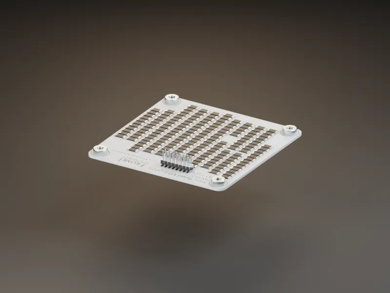
1 The array. The attenuation stages, on a solid aluminium PCB. Each value is made from a group of standard resistors, chosen to land on the panel's numbers. 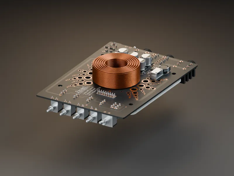
2 The control board. Input, output, the fan circuit and a home for the coil. 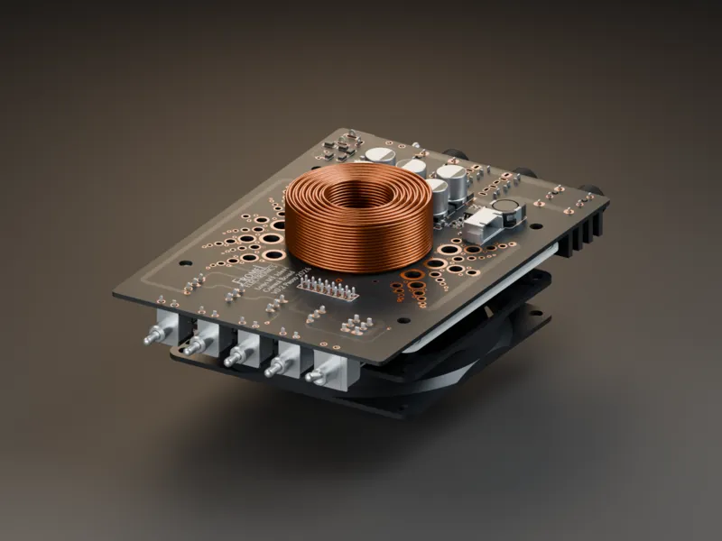
3 The fan. 92 mm fan and 10 mm heat sink. 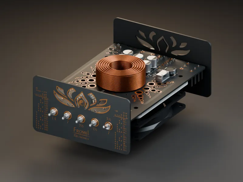
4 The panels. Front and back are circuit boards: matte black mask and exposed copper art. 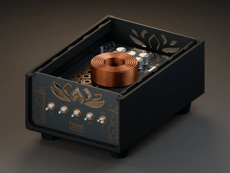
5 The shell. Printed in PET-GF. 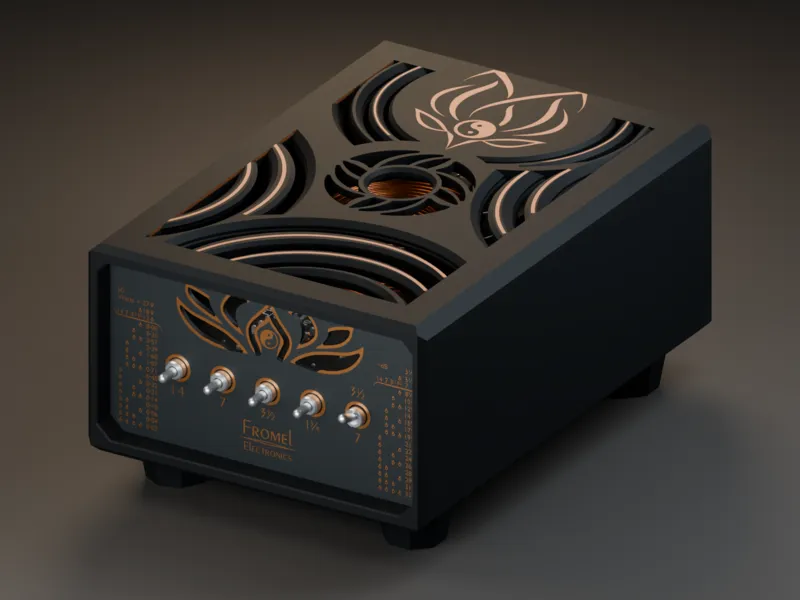
6 The lid. Printed in black glass-filled HTPLA with a copper HTPLA inlay: the lotus, the ripple vents, and a rosette over the coil.
Views
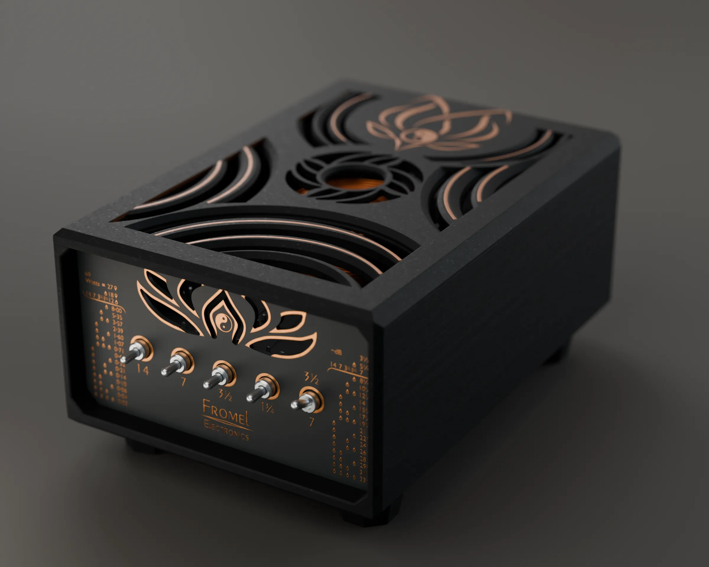
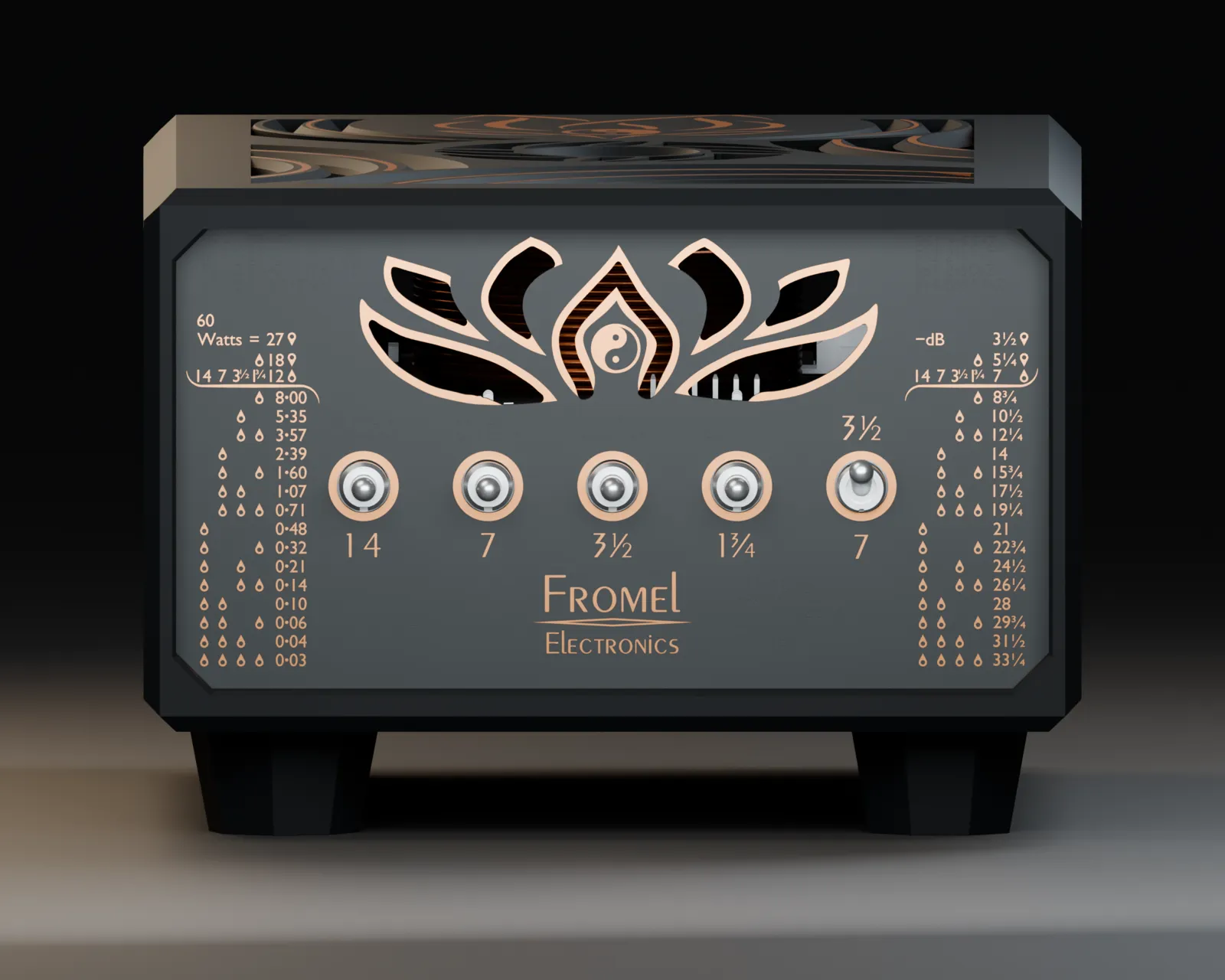
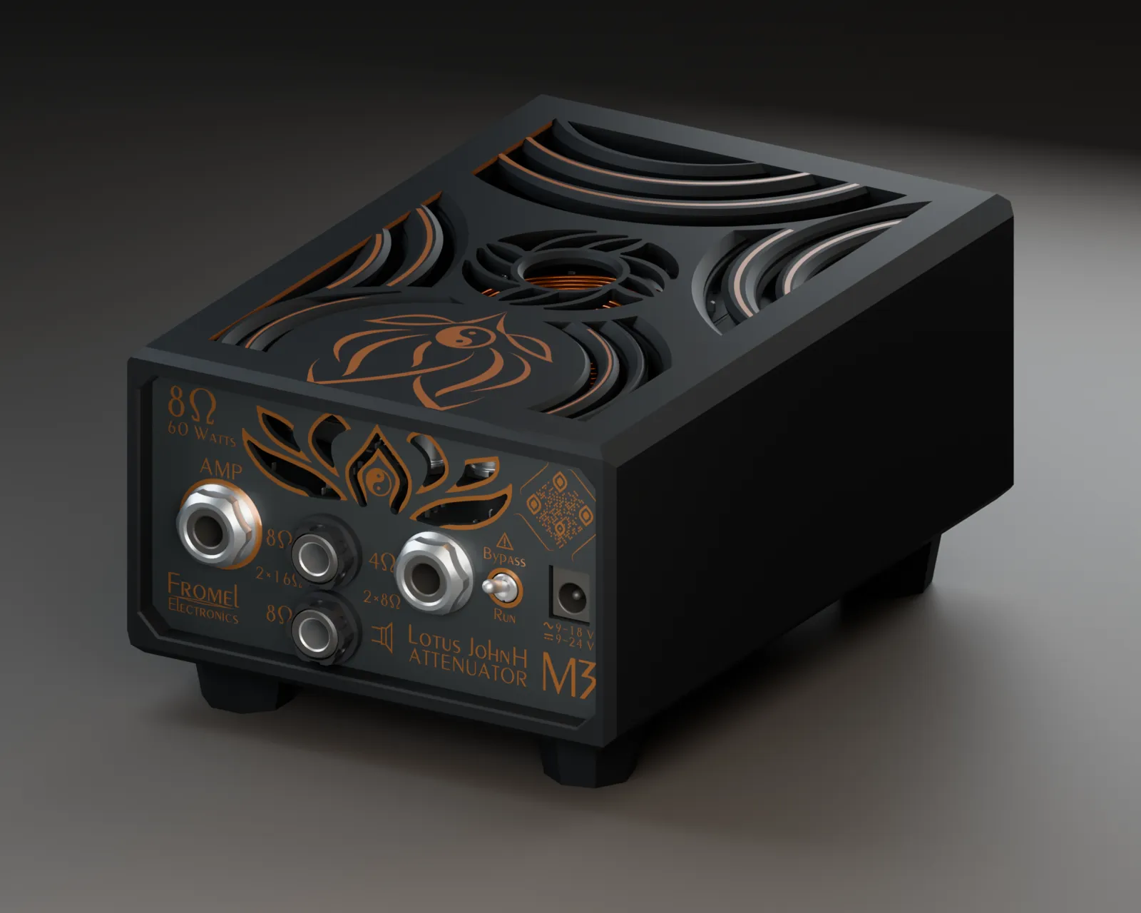
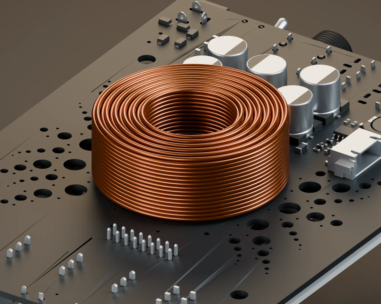
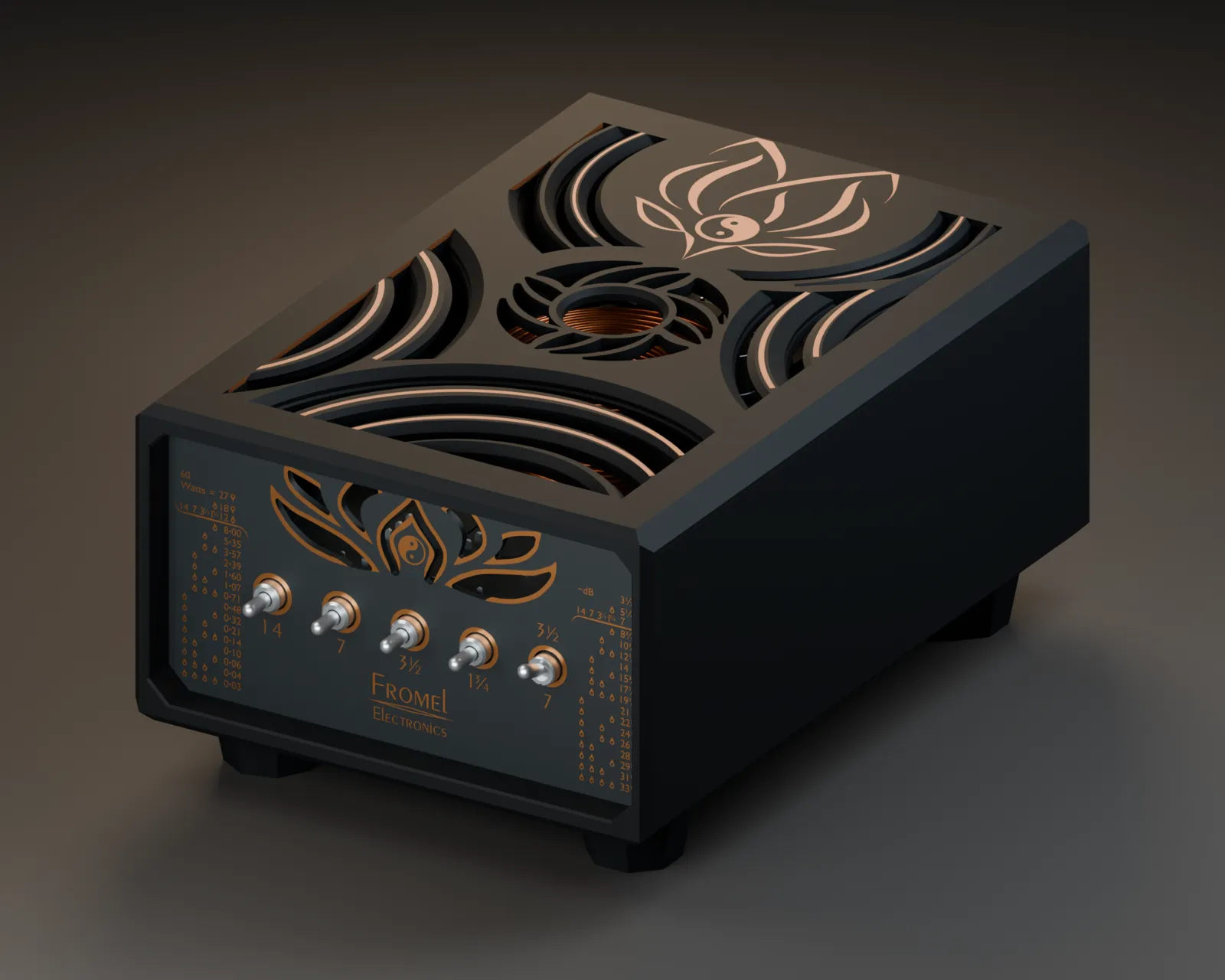
Rendered from the CAD model.